ZipZap said:
wellll ... I just typed a nice response, but the forum timed out and lost it....
Oh yeah, happens every time for me. I always copy-paste to at least my clipboard, or a Word doc, before hitting submit. Can't trust any form unless it has an autosave feature, and the save draft button is not one of those. As a last resort, if you hit back on your browser, there's a good chance what you wrote could be saved in cache. If you copied to clipboard, and then accidentally cleared your clipboard and are using a Windows machine, you can hit the Windows button + V to get your clipboard history I think up to 25 copies.
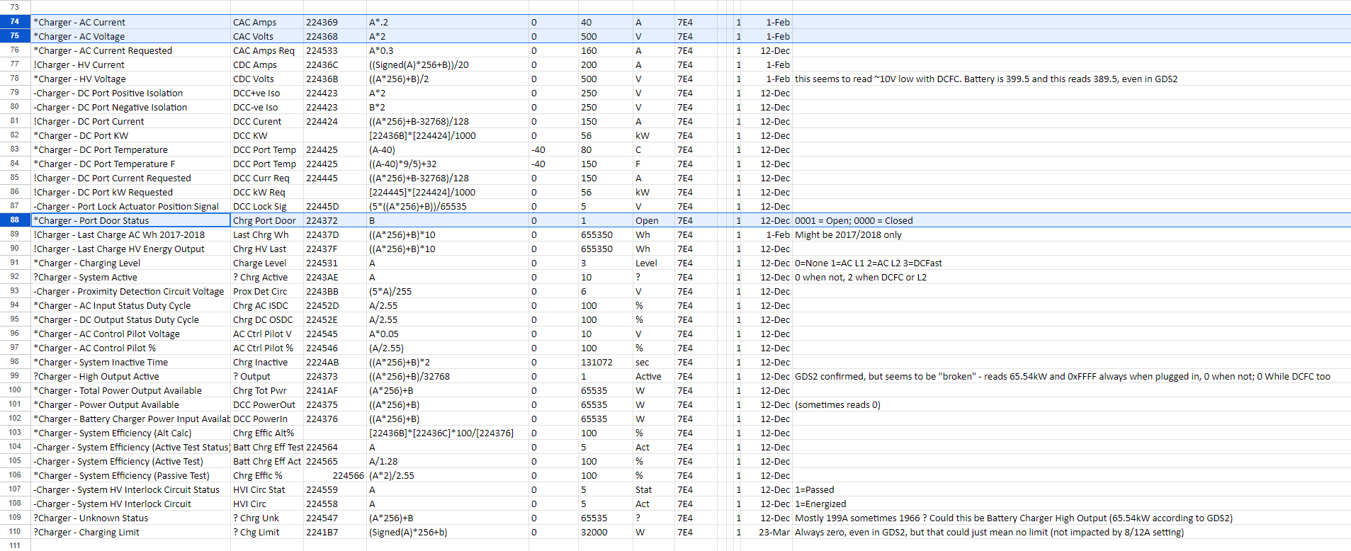
I'm at about 3.29V/cell for the voltage PIDs of the 96cells in the pack (assuming the PIDs are accurate). I'm not sure exactly what that PID in the spreadsheet is actually representative of. The car was at about 10% charge when I encountered the problem. I managed to get a friend of mine over to tow me behind his car and I used regen to get the battery back up to 65% (+ ~5kWh). My battery is down to about 10kWh usable (on the screen onboard) so it's not in great shape, but so far I haven't noticed any large jumps in capacity.
If you have a 2014 Spark EV, then you should have 112 cells in a 112S3P configuration instead of 96 in a 96S2P config. The 112/96 ratio corresponds to the difference in cell voltage between the LFP and NMC packs. 112/96 * 3.6V = 4.2V. This means that the '14 and '15-16 would have the same pack voltage ranges which has certain conveniences.
if the PID title was *Battery - Pack - Minimum Voltage (22433B) instead of what I assumed was -Battery - Pack - Voltage LD (PID 22432d) then it would show the static minimum allowable state of charge for the BMS.
Maybe both your J1772 charge port receptacle pins and your J1772 plug pins are full of gunk
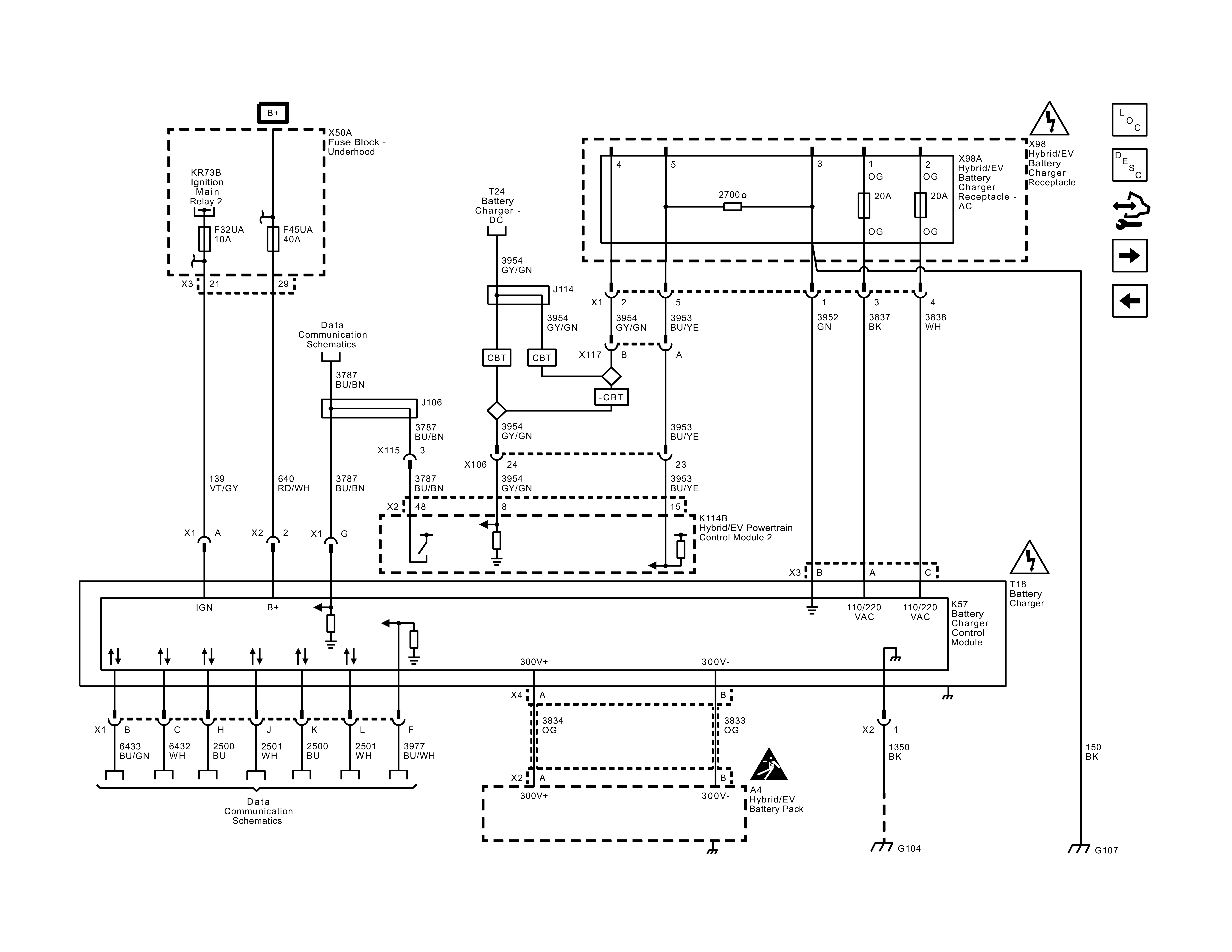
I used a multimeter to measure the resistance of the wiring harness between the pins on the J1772 port and the orange plug that plugs into the onboard charger. For the two AC phase lines, it was as close to zero as the cheapish multimeter could measure. The green center pin on the connector was a little confusing, but it turns out the PE pin of the J1772 plug is only connected directly to the chassis and the green wire from the 3-pin orange plug at the onboard charger just stops at one of the intermediate plugs in the harness. Also, the fuses at the J1772 plug seem fine. There is a picture of my harness below.
Oh, I was mostly speaking to the contact resistance of the mating surfaces between the plug and receptacle. It's good though that you confirmed there is a continuous closed circuit from end-end, though. Anyway, if you press a multimeter probe on the sharp end vs the blunt end, you could get a reading through even an oxide layer or conformal coating. The best diagnosis would be to measure from the end of a J1772 PLUG wire harness to the end of the J1772 RECEPTACLE wire harness with 1A of current flowing through the individual pins on the loop. Measure the voltage drop and you get the line resistance. Pin 4 and pin 5 should have nearly identical calculated resistances, while #1 and #2 should be identical and lower (you can try 8-13A on those pins) resistances. Any variation of the pairs would indicate some difference between them at the connector pin interface or your power supply connections.
That said, a visual inspection would be a bit faster and easier. If it looks dirty or the color isn't a uniform gold, then a contact cleaner and optionally soft non-abrasive brush would be called for.
maybe something happened to the HVCM2 that requires replacing a fuse, reflashing, or replacing, or a high voltage module has gone bad
Yeah, I think there is something hear, but there's a lot here I don't have any great ideas about how to further narrow this down more.
Any pointers on further troubleshooting the HVCM module and onboard charging module? Are there any resources anyone can point me to for the charging system? I've heard rumors that the charging modules are backordered many months (if they are available at all), but I also saw another post on this forum where someone reported they were able to use a Volt charging module without any real modifications.
Whoops, I meant HPCM2 (Hybrid Powertrain Control Module 2, under the driver’s seat), not HVCM2, whatever that is

. Yeah, it’s hard to immediately pinpoint especially if you don’t have any trouble codes. If all the various connectors and wire harnesses are fine and not damaged from any collision or rodents, I would suspect either the on-board charger or HPCM2 from the experiences and descriptions you’ve given.
If it’s the HPCM2, you could channel the hacker in you and pick up a VCX Nano to communicate via GDS2 with the module, and attempt to flash the firmware. It’s a clone of the more expensive dealer scanners that’ve been around for some years now, made in China. I haven’t dabbled with this yet, but I’ll be ordering one myself this week to see what it can do. I just recently heard about such a scanner/programmer browsing the GM-Volt forums as well as the openinverter forums.
The non-DIY programming option is to get the existing HPCM2 flashed at the dealer. Dealerships will be happy to reprogram and replace modules for you, of course, as long as you're programming to the stock VIN.
If it’s the On-board charger (aka the Drive Motor Battery Charger, 24276660), then you should be able to order one from one of the many clone GM e-commerce parts stores that some dealers host, go through a dealer themselves, or again buy used on eBay or a local scrapyard. The Gen 1 Volt and Spark EV’s chargers are nearly identical visually but keep in mind the Spark EV’s coolant ports are straight and connectors are angled, while the Volt will have angled coolant ports and straight electrical connectors in photos.
(Spark EV on-board charger link 1 https://www.tascaparts.com/oem-parts/gm-drive-motor-battery-charger-24276660
Spark EV on-board charger link 2 http://oemcats.com/oem-parts/24276660.html)
Volt Gen 1 on-board charger
https://www.ebay.ca/itm/126114970995
Gen 1 Volt on-board charger in Spark EV was discussed in
viewtopic.php?p=29346#p29344. Tl;dr, Volt chargers work in Spark EVs. The compatibility aspect could be a very interesting discussion for hacking a faster charger.
By tow-charging and driving -- and what an amazing feat that was -- you confirmed that the contactors and inverter are functioning fine, and the high-voltage bus might have proper isolation. That rules out those areas. The HPCM2 needs to operate to give you your data readout as well, so it doesn’t seem fatally corrupted.
I’m leaning heavily toward an on-board charger fault. Maybe a series diode failed open or something. You didn’t mention DCFC charging sessions in your tests, so I have to assume your car uses level 1-2 AC charging only. That’s fine because the tow-charging test proved what the DCFC test would, minus the communication taken care of by the HPCM2.
I'm a bit reluctant to drop $300 on the printed service manual, but maybe it's time to do that. If anyone has one, does it seem like it has useful info for this sort of thing? Does anyone have opinions about how useful the online GM service database might be?
If you’re looking for service manuals, I would recommend getting an online subscription. I use Alldatadiy in 1-month - 1-year intervals. They usually have a 25% discount every other month sent through their email newsletters, you just missed their November discount, unfortunately. The subscription model locks you in for a specific make and model year, so if you wanted to see a schematic for a 2015 Spark EV that uses 96 Li-ion cells instead of the 2014’s 112 cells in series, you’d need two subscriptions.
The subscription is 20 US$ for 1 month, and 60 US$ for a year at their normal prices. However, if you choose Canada as your region, they still value 1 CAD = 1 USD for some reason, so you can save more than their usual sales if they let you order with a US address.
re: usefulness of the online service manuals, the layout and search functionality is faster than the book, and you also have access to service bulletins and part numbers. The only downside is that a few images have had poor resolution but were still somewhat readable. Maybe the book does better in that respect, I don't know.
Has anyone had luck charging the battery with a stand alone power supply/charger? The hacker in me is tempted to try to charge the battery by using an appropriately current and voltage limited power supply connected to the orange 2-pin plug at the onboard charger, but I know it is very likely the onboard charging logic and interconnects won't make that easy (in addition to high voltage safety concerns). Any long term, I don't want anything that's too much of a hassle. Are there other methods anyone has had success with?
Real Solar Cars on YT has charged their Chevy Volt pack with his custom solar MPPT charger mod. He engages the contactor coils and charges the pack with up to I think 300W of power with his custom DC-DC solar charge controller. Not really a hassle-free solution for you, though.
If you provided 90-250V AC or DC to the input pins of the charger, it would still require some enumeration with the HPCM2, which is responsible for programming the on-board charger’s input current limit, and yes, energizing the contactors. That’s in theory, at least. Who knows if it would default to charging at the lowest current on the chance that communication fails, but power is present? I’m not aware of anyone who’s tried injecting power onto the power pins of the Spark EV. If you have the Open EVSE, you could try to safely bypass the internal relay unit so that AC voltage is present without a J1772 protocol handshake. Again I’m not sure what would happen, and I’d be inclined to believe an out-of-sequence handshake would raise digital eyebrows in the computers. But nothing is going to blow up. Worst case, the on-board charger would operate, and the output would reach its ~400V OVP threshold on the high voltage bus. If you do try it, a VCX Nano might come in handy in case a MIL and trouble code comes on that can't be cleared through OBD II and needs to be cleared through GDS2.
If it does end up working, it won’t be a very sustainable solution as your home will turn into the only place you can charge… But it would confirm the charger is operating, and there might instead be a communication problem.
Here's a picture/diagram of my wiring harness from the J1772 plug to the orange plug that connects to the onboard charger.
Here's a Plug-In Charging schematic to go with it.


